Every process stage needs a reason.
Each section must support the confirmed board, capacity, material behavior, quality target or downstream requirement.
ENGINEERING / ENGINEER / BOARD PRODUCTION LINE ARCHITECTURE
The Engineer stage converts defined board specifications, raw-material conditions, capacity targets and factory constraints into a coordinated architecture covering process sequence, equipment configuration, controls, utilities and material flow.
FROM APPROVED BASIS TO EXECUTABLE ENGINEERING
Each section must support the confirmed board, capacity, material behavior, quality target or downstream requirement.
Equipment transfers, control signals, utilities, buffers, operator access and maintenance space are coordinated as one environment.
Layouts and construction references must give manufacturing and the customer’s local site team a consistent basis for parallel work.
SYSTEM BLUEPRINT
The architecture begins with process logic, then defines equipment, controls and the physical connection to the factory.
Connect raw-material preparation, mixing, forming, curing, demoulding, finishing and deep processing.
Define required systems, optional modules, customer-supplied equipment and interface responsibilities.
Map PLC sequences, operating modes, sensors, interlocks, alarms, buffers and HMI access.
Position systems around available space, logistics, storage, utilities, access and future expansion.
ENGINEERING CONSOLE
Select a control card to switch the engineering focus of the main visual.
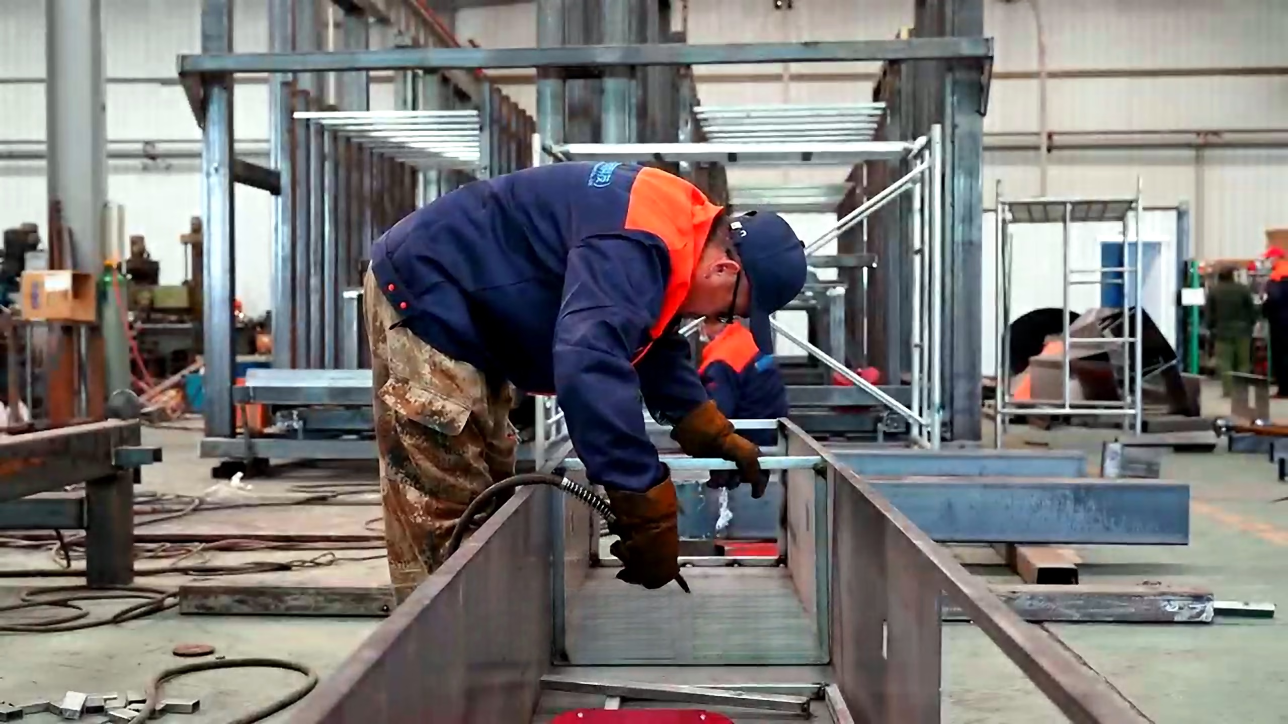
Build the operating sequence from material preparation and forming through curing, demoulding, finishing and deep processing.
Board-production stages and material movement from raw-material input to finished output.
Functional systems configured around formulation, capacity and product specification.
PLC coordination, sensors, interlocks, operating modes, alarms and production data.
Layout, utilities, storage, access, logistics and existing-equipment interfaces.
DESIGN LAYERS
The same equipment can perform differently depending on formulation, process timing, layout, automation and service access.
Raw-material variation, formulation stability, moisture, fiber condition, setting behavior and forming sensitivity.
Production stages, working width, cycle requirements, buffers, handling method and maintenance access.
Dosing, feeding, forming, transfer, curing, demoulding, finishing and stacking coordinated around output.
Cleaning, inspection, wear parts, fault diagnosis, safe access, spare parts and operator training.
INTERFACE MAP
Factory utilities, logistics and operator access are part of production performance—not external details.
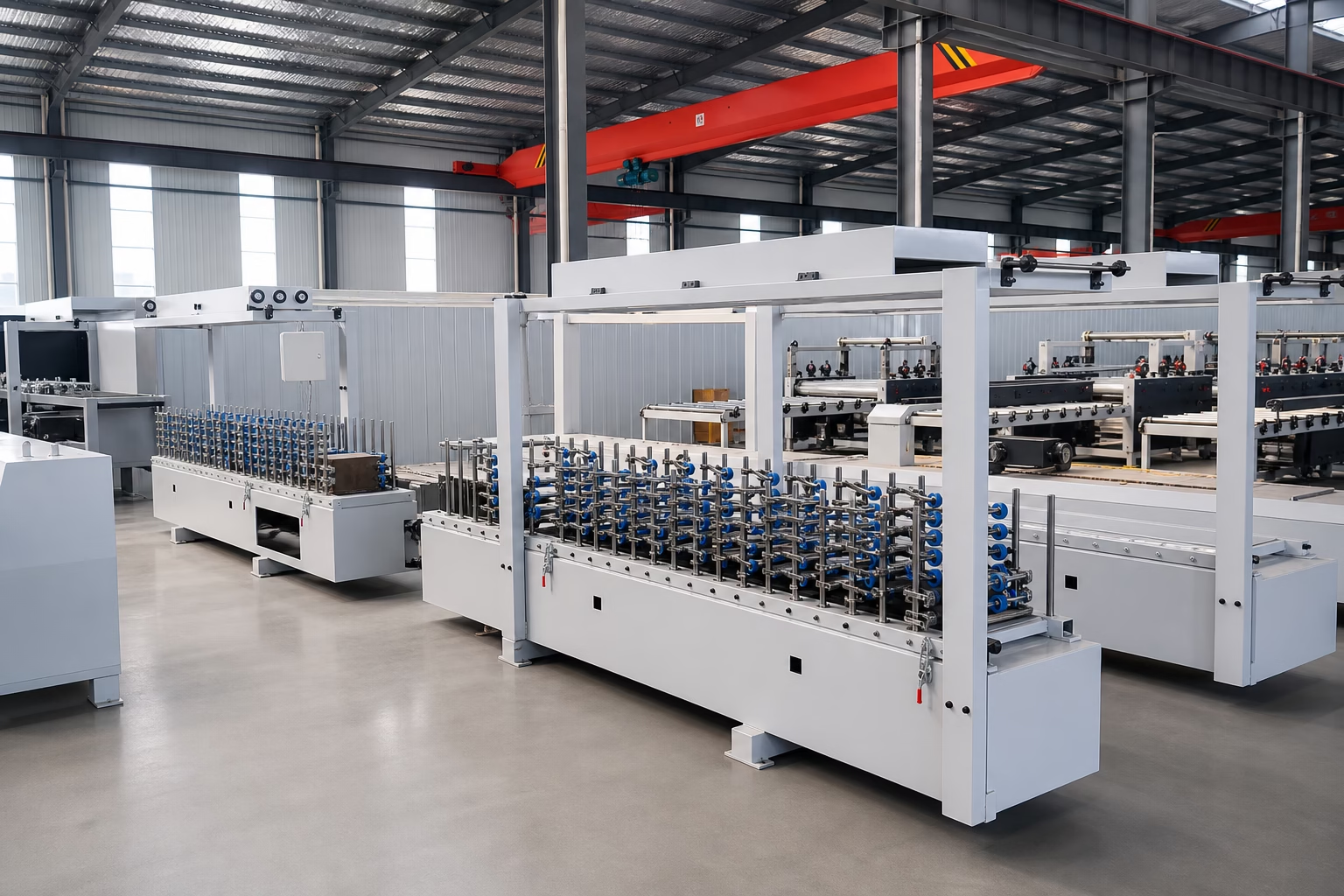
Receiving, storage, powder and fiber handling, dosing, feeding and formulation control.
Power, water, compressed air, dust collection, drainage, curing utilities and environment.
HMI position, inspection access, safety zones, platforms, maintenance routes and emergency controls.
Demoulding, curing transfer, sanding, cutting, deep processing, packing and warehouse connection.
ENGINEER STAGE OUTPUTS
Engineering outputs keep manufacturing, assembly, controls and acceptance testing aligned around the same production basis.
Continue to Build →Defined sequence, selected systems, functional modules and supply boundaries.
Equipment position, material flow, buffers, storage, operator routes and maintenance clearance.
PLC coordination, operating modes, sensors, HMI, alarms and safety interlocks.
Factory services and upstream, downstream and control connection requirements.
Critical drawings, performance criteria, inspections, trials and FAT requirements.
READY TO ENGINEER THE PRODUCTION LINE?
Share the defined board specification, formulation, capacity, process scope and factory conditions. Our engineering team will develop the production route, equipment architecture, controls and interface direction.