
Mixing, Forming & Curing
How to Configure
a Board Forming System
A practical framework for controlling material handover, working width, thickness, surface quality and downstream transfer before equipment configuration begins.
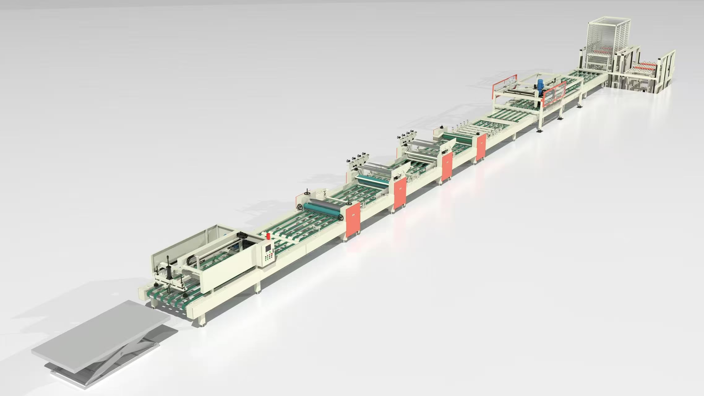
ARTICLE SUMMARY
A forming system creates board geometry and structure; later machinery cannot reliably repair unstable formation.
The forming section converts prepared material into a continuous board with controlled width, thickness, surface condition and transfer state.
Stable results depend on material handover, distribution, working geometry, production rhythm and documented process control—not on one machine setting alone.
01 — START WITH THE FINISHED BOARD
Specify the required output
before the forming machine.
A forming system should be specified from the finished-board requirement backward. Two factories may both produce construction board but need different arrangements because their material behaviour, thickness range, board format, handling route or capacity target is different.
Connect the initial project brief to the agreed production line requirements. This prevents the forming section from being selected as an isolated machine while the complete route remains undefined.
ENGINEERING PRINCIPLEThe machine name is not a process definition. Start with the board the factory must sell and the condition required by the next production stage.
02 — DEFINE MIXING HANDOVER
Forming stability begins
before material arrives.
A stable feeding and mixing system should deliver the required material condition at an agreed rhythm. The forming team needs a practical handover definition—not merely confirmation that every ingredient was added.
Discharge condition: Define what the mixture must look and behave like before release.
Transfer time: Set relevant limits between preparation and forming.
Transfer route: Define how material reaches and enters the forming section.
Warning signs: Identify changes in appearance, moisture or flow that require investigation.
Change authority: State who may alter recipes, sequences, rates or operating settings.
Uneven distribution, thickness variation or unstable edges may originate in material identity, dosing, mixing sequence, transfer timing or batch consistency. Trace the full process before repeatedly adjusting the forming machine.
Material preparation, distribution, geometry control and downstream transfer must operate as one coordinated system.
03 — CONFIGURE BOARD GEOMETRY
Design around the real
board-format range.
Board dimensions influence the forming width, support arrangement, transfer direction, tooling concept, conveyor interface and handling space required throughout the line.
Working width
Define usable width, format range and allowance for edge control or trimming.
Thickness range
Define nominal values, permitted variation and validated change procedures.
Board structure
Confirm layers, reinforcement and internal-structure requirements.
Surface & edges
Specify the state required before sanding, coating or secondary processing.
The purpose is not to promise a result from a generic setup. It is to identify the operating variables that must be controlled, trialled and documented for the customer’s actual board.
04 — CONTROL MATERIAL DISTRIBUTION
Control distribution before
correcting thickness.
Thickness stability depends on even material distribution across the working width and along the production direction. If incoming material is inconsistent, later pressing, cutting or sanding may increase waste rather than solve the original variation.
When configuring a board forming system, agree on checks for width, thickness, surface uniformity, edge condition and transfer behaviour. Research into cement-fibre board manufacturing describes how controlled layer accumulation contributes to required thickness and structure. Review the published research.
05 — MATCH PRODUCTION RHYTHM
Every handover must support
the next process.
The line should not produce prepared material or newly formed board faster than the next section can receive, condition or transfer it.
| Interface | Question to define |
|---|---|
| Mixing to forming | Is material supplied at a repeatable condition and timing? |
| Forming to conditioning | Can the board be supported without distortion or unnecessary interruption? |
| Conditioning to release | Is the board at the required state for separation or demoulding? |
| Forming to cutting | Do dimensions, direction and support match the sizing route? |
| Forming to finishing | Is the board condition suitable for sanding, coating or lamination? |
The handover to a controlled board demoulding system deserves particular attention because incorrect separation direction, lifting method or conveyor rhythm may mark or deform a vulnerable board.
LINE-STABILITY PRINCIPLEA stable line is not one where every section runs at maximum speed. It is one where every section supports the next at an agreed, repeatable rate.
06 — INVESTIGATE VISIBLE SYMPTOMS
Use defects as prompts,
not automatic diagnoses.
Confirm causes through observations, process records and controlled trials before changing the approved process.
| Observed condition | Items to investigate before changing settings |
|---|---|
| Thickness variation | Material consistency, width distribution, forming setup, line speed and transfer support |
| Uneven surface | Material dispersion, entry route, forming surface, support and contact points |
| Inconsistent edges | Edge distribution, tooling condition, board support and trimming assumptions |
| Instability after forming | Material condition, thickness, conditioning, transfer timing and support route |
| Frequent adjustments | Missing standards, unclear authority, incomplete records or unstable upstream supply |
| Downstream damage | Board orientation, conveyor speed, support method and section interfaces |
Published work has also investigated delamination as a fibre-cement board manufacturing-quality issue. Read the board quality assessment study.
07 — COMMISSION THROUGH CONTROLLED TRIALS
Verify the route against
a defined board specification.
Begin trial production with an agreed basis instead of an open-ended attempt to “make a board.” During trials, change one meaningful variable at a time where practical and record the effect.
Approve the input route
Confirm the material list and handling conditions.
Set the trial board
Define dimensions, thickness and intended surface condition.
Prepare forming geometry
Confirm width, tooling and transfer direction.
Control speed and start-up
Use an agreed line-speed basis and sequence.
Measure the board
Check thickness, width, surface and edge condition.
Record changes and results
Build a repeatable operating basis rather than relying on memory.
08 — BUILD A FORMING RECORD
Repeatable production needs
a repeatable record.
For every approved board route, retain a concise process record connecting material preparation, forming and downstream transfer.
DEFINE THE FORMING ROUTE
Configure forming as part of the complete production line—not as a stand-alone purchase.
Provide the finished-board specification.
Define the raw-material preparation route.
Confirm thickness and board-format ranges.
Set target output and production rhythm.
Provide the factory layout and utilities.
Define downstream processing and handling.
With these inputs, the engineering team can develop a forming concept that fits the complete line.
Review building board engineering →