Receive & store
Plan raw-material receipt, identification and controlled storage.
Material route / Calcium silicate board
Plan the line around the board range, material system, forming and conditioning route, finishing requirements, output basis and real factory conditions—not a generic equipment list.
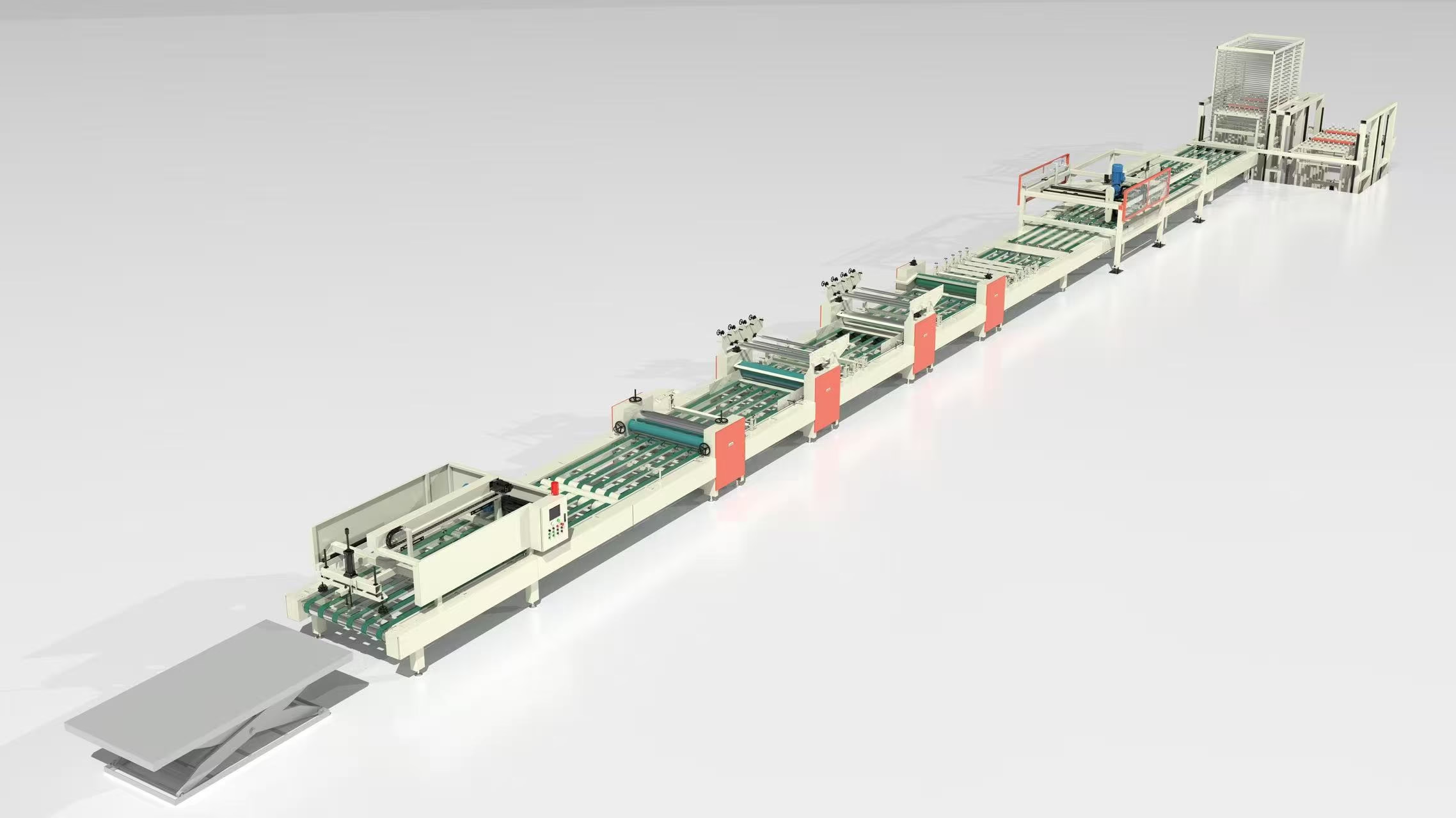
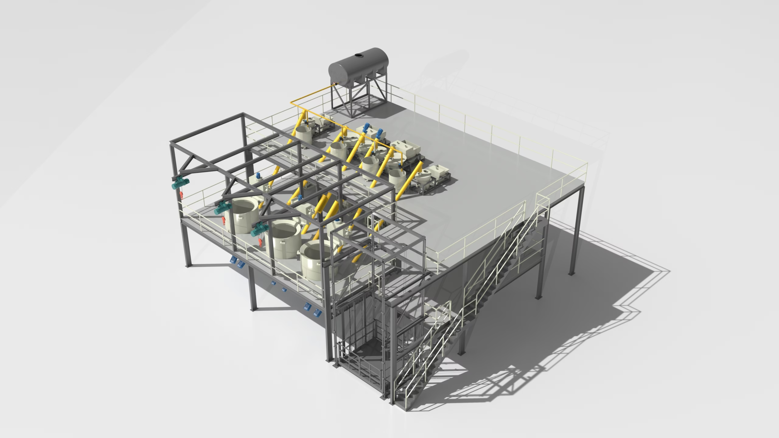
A production system, not a machine list
Process route / from inputs to finished boards
The route below is a planning framework. Confirm which stages apply to the chosen formulation, board specification and operating concept; identify optional processes separately from the core line scope.
Plan raw-material receipt, identification and controlled storage.
Define dosing, feeding and mixing around the material system.
Coordinate transfer from preparation into the forming section.
Review forming method, thickness setting and board support.
Confirm demoulding and required curing or conditioning steps.
Include sizing, sanding and inspection as required by product.
Plan handling, packing, storage and finished-goods movement.
ROUTE BOUNDARYShow which stages are confirmed, formulation-dependent or optional. Optional finishing should be connected to a defined finished-product requirement, not assumed as standard scope.
PRODUCT BASIS / MATERIAL ROUTE01 / Define the product first
“Calcium silicate board” is not a complete production requirement. Record the target product range and operating conditions so the line concept has a clear reference point.
If several sizes or product variants are planned, identify the main operating condition and list changeovers or special cases separately. This helps distinguish the base line concept from provisions that may affect flexibility, process interfaces or project scope.
Project definition / manage uncertainty
Incomplete early information is normal. The important part is to label it clearly and track decisions that could change process scope, equipment selection, layout or capacity.
Information supported by drawings, specifications, material data or established production records. Use these inputs as the current design basis.
Values suitable for concept development but requiring review or approval. Mark the owner and the point at which confirmation is needed.
Examples include material preparation responsibility, product changeover frequency, storage duration, finishing level and auxiliary-system boundaries.
GOOD PRACTICECarry each assumption into the proposal and decision log instead of burying it in a general equipment description.
Capacity / comparable planning basis
Capacity statements are only comparable when the reference product, operating hours, product mix, changeovers and output definition are aligned.
State whether a figure is theoretical, planned or saleable output and which board size and thickness it uses. Treat the line as a balanced route from preparation through downstream handling.
Dimensions, thickness and product variant used for the calculation.
Hours per shift, shifts per day and expected operating pattern.
Planned changes in size, thickness, formulation or process settings.
Identify the stage most likely to govern overall production rhythm.
LINE BALANCEA faster individual machine does not automatically increase finished-board output when conditioning, transfers, cutting or stacking remain constrained.
Factory planning / before positions are fixed
Factory conditions affect orientation, intermediate transfers, operating access and future expansion. Provide available site information early so constraints and unknowns can be reviewed before equipment positions are finalised.
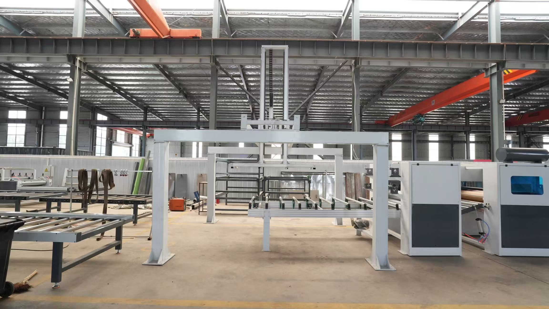
FACTORY CONDITIONS / SITE INPUTSMaterial preparation / forming interface
Preparation equipment should be considered as part of the whole process route. Review material handling, controls, transfer distances and what happens when a downstream stage pauses.
Document material types, delivery forms, storage needs and the dosing considerations provided by the project owner.
Discuss sequence control, mixing-time basis and how preparation is coordinated with board forming.
Review transfer distance, cleaning requirements and response to a downstream interruption.
RELATED SYSTEMSee the feeding and mixing system as one route component, with the forming and transfer interface kept in view.
Verification / before delivery
Plan how the agreed scope will be checked. The verification basis should fit the contracted equipment and the conditions that can realistically be reproduced before shipment.
Confirm the current project basis, interfaces, revisions and agreed arrangement.
Review the supplied modules and options against the documented scope.
Agree which control functions and sequences can be reviewed under factory conditions.
Define the records, observations and evidence that will be retained.
Assign each open item an owner, next action and appropriate review stage.
PROJECT CONTROLRecord changes against the same reference used by the owner, engineering team and supplier so the approved basis remains traceable.
Prepare for a technical discussion
Share what is known and mark what remains provisional. If an input is unavailable, identify who can confirm it and when.
Application, dimensions, thickness, density or surface expectations where available.
Raw-material information, formulation status and preparation responsibilities.
Reference product, shift schedule, product mix and output definition.
Forming, conditioning, demoulding, finishing and handling requirements.
Factory drawing, utilities, access, receiving and finished-product movement.
Automation preference, project location, timeline and open decisions.
Start with your board requirement
Send your board range, material information, target output and factory drawing. The next step is to confirm the design basis before equipment configuration.
Board dimensions, thickness, material route and finishing requirements influence the process stages and equipment interfaces. A generic equipment list cannot represent every product condition equally.
Yes. Label it as provisional, note the basis and track who will confirm it and by when. Assumptions that affect scope, layout or capacity should be reviewed before final configuration.
Include the reference board, operating schedule, product mix, changeover assumptions and whether the figure describes theoretical, planned or saleable output. This makes proposals more comparable.
As early as possible. A preliminary dimensioned drawing can reveal constraints involving line direction, material flow, access, utilities and expansion before equipment positions are fixed.
Connect each optional process to a defined finished-board requirement. State whether it is part of the confirmed line scope, a future provision or still under evaluation.