
Board Production Planning
Building Board Production Line
Factory Layout Checklist
What to confirm about building dimensions, material flow, utilities, installation access and future expansion before equipment configuration is finalised.
ARTICLE SUMMARY
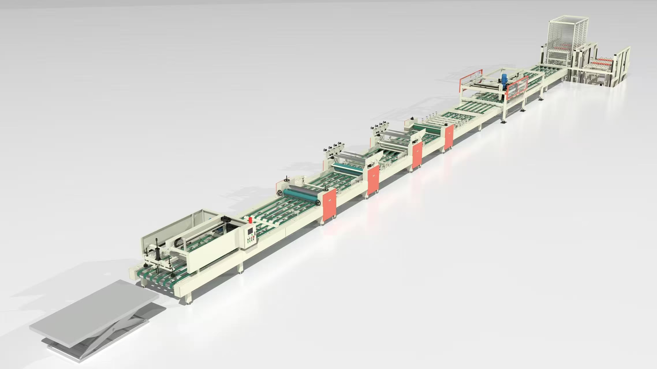
The factory affects equipment arrangement, installation, material movement and the room left for future production.
A production line is not configured from capacity alone. The site influences equipment sequence, utility routing, access, maintenance and handling conditions.
A preliminary floor plan, key dimensions, photos and process route are enough to begin a useful engineering review. Mark provisional details so they are not mistaken for confirmed site measurements.
01 — START WITH THE PRODUCTION ROUTE
Map the process before
placing equipment.
An empty building may look large enough, but usable space depends on how materials, operators, equipment and finished boards move through it. Start with the intended route from receiving to dispatch, then review how each handover fits the site.
Receive & store materials
Plan unloading, raw-material storage and movement to preparation.
Dose, feed & mix
Connect storage, preparation and transfer to the forming area.
Form & transfer board
Allow for the forming equipment, working access and initial support.
Cure or treat
Include conditioning, treatment or curing where the product route requires it.
Demould & handle
Plan board release, transfer and any defined staging area.
Cut, size & finish
Connect sizing, edge processing, sanding and optional finishing.
Inspect, pack & dispatch
Reserve space for stacking, finished goods and loading.
This sequence is a planning framework; the actual route depends on board type, material system and required finished condition. Review the complete board production plan to connect product requirements and equipment stages.
LAYOUT PRINCIPLEUse the floor plan to support the production sequence, not to decide the sequence by whatever spaces happen to remain.
02 — CONFIRM THE BUILDING ENVELOPE
Measure usable space,
not only floor area.
The first site review should record physical limits that can affect equipment size, movement, installation and operation. Total square metres alone do not show whether a line can be delivered or safely accessed.
Check clear height against roof trusses, lights, ducts and other overhead items. Mark the equipment delivery route from the unloading point to the planned installation location, including turns around columns and door openings.
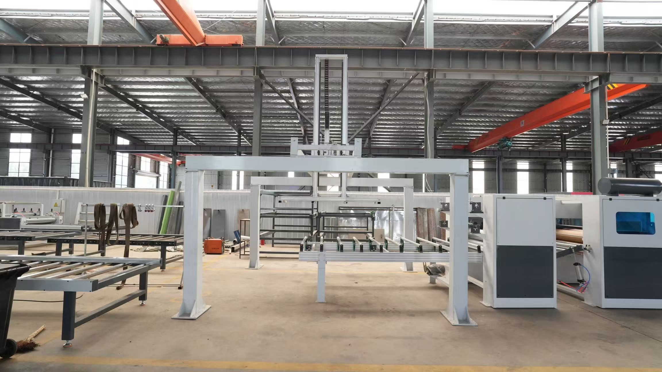
Allow the production route, people, material movement and service access to coexist within the available space.
03 — PLAN MATERIAL FLOW AS ONE DIRECTION
Reduce crossings and
unplanned handling.
Where practical, plan one primary direction from receiving to dispatch. Keep people, forklifts, maintenance access and finished-board movement in view while positioning each production section.
Raw materials
Show delivery access, temporary storage and transfer to feeding and mixing.
Mixing to forming
Keep preparation and forming connected with a practical transfer route.
Forming onward
Allow for conditioning, release, cutting and defined staging areas.
Finished goods
Connect inspection, stacking, packing, storage and dispatch.
Repeated forklift crossings, returns to earlier stations and undefined waiting zones can create handling pressure. A buffer may be necessary, but give it a defined purpose, size basis and location instead of using the only aisle as storage.
Before fixing upstream positions, confirm the production line requirements. Board type, dimensions, material route, output target and automation level all affect the preferred arrangement.
04 — CHECK UTILITIES AND ENVIRONMENTAL INTERFACES
Map service locations
before finalising the layout.
A machinery arrangement is incomplete until its utilities and environmental interfaces are considered. Requirements depend on the board, process route and equipment scope, so identify what exists and what still needs site-specific confirmation.
| Interface to map | Site information to prepare | Review question |
|---|---|---|
| Electrical supply | Known supply details and cable-routing paths | Where can supply and distribution reach the equipment? |
| Process and cleaning water | Available connection locations and known conditions | Which process areas need water access? |
| Drainage | Drain locations, floor channels and discharge route | Do drainage points align with planned work areas? |
| Compressed air | Existing source and distribution route, if available | Can distribution reach the required equipment interfaces? |
| Ventilation and extraction | Existing or planned extraction interfaces | Where must ducts or environmental systems connect? |
| Controls and panels | Potential locations and operator access routes | Can controls be reached without blocking material flow? |
Do not assume an existing utility point is automatically suitable for a new line. Location, capacity, routing distance and compatibility still need review during the project requirements and materials stage.
LOCAL SITE REVIEWApplicable electrical, environmental, fire, construction and workplace-safety requirements vary by location. Confirm them with appropriately qualified local parties before civil works or installation decisions are finalised.
05 — RESERVE INSTALLATION, OPERATION AND MAINTENANCE ACCESS
Design for the people
who use and service the line.
A compact floor plan can appear efficient while making normal operation difficult. Include guarding, platforms, control cabinets, material containers and service access in the review, rather than drawing only machine footprints.
Delivery: Can equipment be unloaded, moved and positioned along a clear route?
Operation: Is there an accessible side for routine adjustment and inspection?
Controls: Can operators reach control points without blocking product flow?
Cleaning: Is there practical access around the areas that require regular cleaning?
Service: Can components that need inspection or replacement be reached?
Traffic: Are forklift routes, lifting needs and pedestrian movement considered?
Quality checks: Where will samples, rejected boards and in-process checks be handled?
Review the relevant building board production line modules as connected stages, then consider the access needed for each stage in its actual site position.
06 — KEEP EXPANSION OPTIONS VISIBLE
Protect the next phase
while planning the first.
Not every process module needs to be installed on day one. Mark plausible future areas on the layout so the first-phase arrangement does not occupy the only practical expansion zone.
Mark these areas as possible future provisions rather than part of the confirmed scope. This makes the current boundary clear while keeping later planning visible.
07 — PREPARE THE LAYOUT PACKAGE
A useful first review can
start with simple materials.
You do not need a final engineering drawing to begin. Send what is available and label assumptions, unknown dimensions and items that need a site check.
| Information to provide | How it supports layout review | Status to mark |
|---|---|---|
| Floor plan or hand-drawn layout | Shows usable space, columns, doors and routes. | Current / preliminary |
| Building length, width and clear height | Supports equipment arrangement and installation access review. | Measured / estimated |
| Door and loading-bay dimensions | Helps assess delivery and movement of equipment modules. | Confirmed / to measure |
| Workshop photographs | Clarifies visible site conditions and obstructions. | Date and location if known |
| Board type and dimensions | Connects the layout to the required process route. | Confirmed / target range |
| Capacity and operating pattern | Informs line rhythm and possible buffer areas. | Target / planning basis |
| Available utilities | Highlights interfaces that need further confirmation. | Known / needs verification |
| Material and finished-goods direction | Supports a logical movement path through the site. | Planned / open |
| Future expansion plans | Protects possible process connections and space. | Possible / approved |
08 — REVIEW BEFORE EQUIPMENT CONFIGURATION
Use a staged review to
close site questions.
Organise the layout discussion so each decision has a clear basis. The early review identifies questions; later drawings should reflect confirmed dimensions and agreed scope.
Assemble the site information
Gather plan, dimensions, photographs and known utility data.
Confirm product and process route
State the board, target output and first-phase process scope.
Review traffic and interfaces
Trace materials, boards, people, utilities and service access.
List open site items
Mark dimensions and requirements that need measurement or local confirmation.
Develop the equipment arrangement
Use confirmed inputs to prepare the next configuration basis.
Keep preliminary planning and final installation documentation clearly distinguished. Final civil works and site decisions should follow the approved project drawings and the applicable local review process.
09 — FACTORY LAYOUT REVIEW CHECKLIST
Before layout approval,
confirm these nine points.
TURN SITE INFORMATION INTO A PROJECT DISCUSSION
The goal is a workable production route that fits the real factory conditions.
Share the floor plan, dimensions and site photographs.
Describe the board, materials and target output.
Map the intended process route from receiving to dispatch.
Identify utilities, access constraints and existing equipment.
Mark measurements and decisions still needing confirmation.
Reserve any realistic future expansion area.
If you have a floor plan, workshop dimensions or site photographs, use them as the starting point for an engineering review. Once the project moves from layout confirmation to equipment completion, use the factory test preparation checklist to define the pre-shipment review, records and remaining site-dependent items.
Start a project with MGO Equipment →